Bizarro Homer User Manual
Table of Contents
*** signifies a MUST READ Section.
- Section 0: Introduction ***
- Section 1: Safety ***
- Section 2: Robot Operation ***
- Section 3: Low Battery Precautions ***
- Section 4: Storage ***
- Section 5: Troubleshooting
- Section 6: Software Overview
- 6.1: Main Control Program
- 6.1.1: Systemd Service
- 6.1.2: Controls Class
- 6.1.3: Drive Class
- 6.1.4: Shooter Class
- 6.1.5: AirTank Class
- 6.1.6: ShooterPivot Class
- 6.1.7: ShooterBarrel Class
- 6.1.8: DualShock4 Class
- 6.1.9: thunder::DigitalInput and thunder::DigitalOutput Classes
- 6.1.10: thunder::ThroughBore Class
- 6.1.11: thunder::SparkMax Class
- 6.1.12: thunder::PressureTransducer Class
- 6.1.13: thunder::LEDStrip Class
- 6.1.14: Dashboard Server
- 6.2: Dashboard
- 6.1: Main Control Program
- Section 7: Hardware Overview
- Section 8: Raspberry Pi Stuff
Section 0: Introduction
Must Read
The T-Shirt Shooting robot (a.k.a. Bizarro Homer) is constructed specifically for use at robot demos. Because of this, the robot was designed, wired, and programmed vastly differently than any other robot the team has ever built. This user manual should help team members understand this robot in detail, including how to operate it, safety measures, and troubleshooting tips.
It is strongly recommended (by Peter) that a copy of this manual gets taken to every demo with the T-Shirt robot.
The T-Shirt robot is (by far) the most dangerous robot the team has ever built. The robot stores 3000 PSI of pressure, so everybody at a demo should be aware of the safety measures outlined in Section 1.
It is strongly recommended that everybody using this robot reads through the first four sections.
The remaining sections include troubleshooting information, software details, and more technical information about the robot. This user manual includes enough information to become an expert at this robot.
Section 1: Safety
Must Read
The T-Shirt robot stores 3000 PSI of pressure, making it quite dangerous. It is essential to always be careful when operating the robot.
1.1: General Safety Measures
- NEVER turn off the robot with stored pressure in the fill tank. Always shoot before turning off the robot.
- When pressurized, everybody should be at least 5 feet away from the robot.
- There is no “disabled” state for this robot. Whenever it is on, it is enabled. Always be cautious. Never lose track of the controller.
- NEVER reload the shooter with stored pressure in the fill tank. Also, don’t let anybody touch the controls when reloading.
- Only team members should be driving the robot at demos. DO NOT hand the controls over to a small child.
1.2: “Robot” Safety Measures
- Follow the startup procedure outlined in Section 2.1.
- It goes without saying, but never let this robot get wet.
- If the electronics get wet, be 100% sure that they are dry before powering on the robot.
Section 2: Robot Operation
Must Read
2.1: Startup Procedure
2.1.1: Initial Shooter Position
Before the robot boots up, ensure the shooter is at its home position (0˚ angle, flat with the ground). The robot cannot remember the shooter’s angle when off, so every preset position is based on what’s read at startup. For more information about how the pivoting works, refer to Section 6.1.6
2.1.2: Battery
The T-Shirt bot can only use batteries with terminals flush with the top, like the batteries used in the 2023 robot. Batteries with leads sticking out of the top will not fit.
Before placing the battery in the robot, place the battery strap around the battery to allow for easier removal of the battery from the robot.
2.2: Robot Power On and Connecting the Controller
A singular DualShock4 Controller is used to control the T-Shirt Shooting robot.
When the robot boots up, press the center Playstation button on the controller to turn on the controller. The controller should start flashing white, which signifies that the controller is looking for the robot. When the robot finishes booting up, the controller should automatically connect to the robot, and the LEDs on the controller should change to the current robot state (described in Section 2.4). If the LEDs turn off, that probably means the controller timed out connecting and turned itself off. Just press the PlayStation button again to turn it back on.
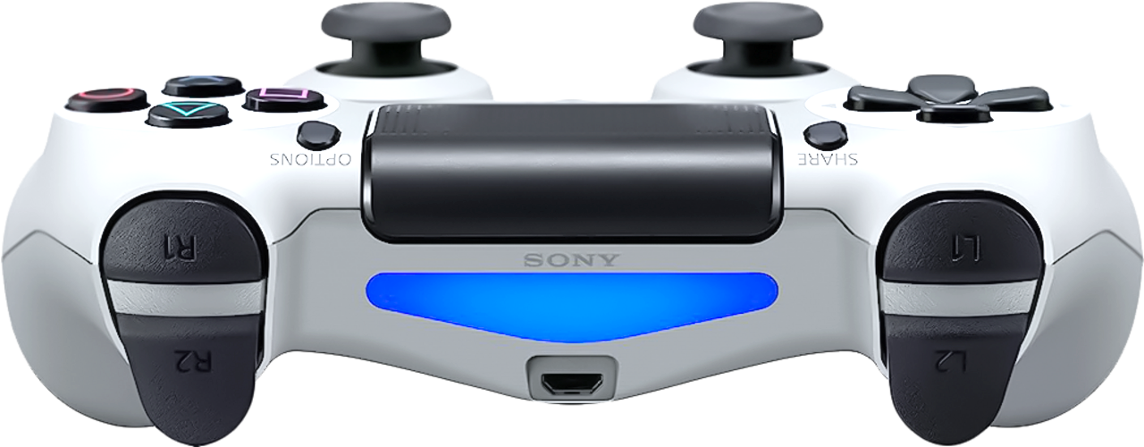
Plug in the DualShock4 controller to the Raspberry Pi for a wired connection if Bluetooth isn’t working. Make sure you have a long enough micro-USB cable!
2.3: Controls
As per safety precaution #5 (see Section 1), Only team members should be driving the robot at demos. DO NOT hand the controller over to a small child.
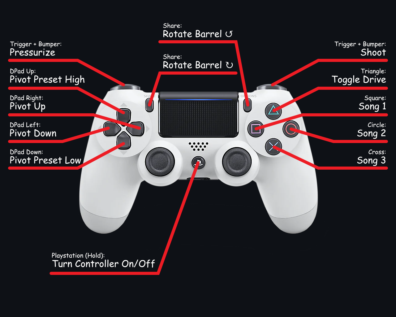
| Input | Description |
|---|---|
| Left Joystick | Tank: Up/Down → Left drive Arcade: Up/Down → Drive forwards/backwards |
| Right Joystick | Tank: Up/Down → Right drive Arcade: Right/Left → Turn left/right |
| DPad Up | Shooter Preset High |
| DPad Right | Shooter Manual Raise |
| DPad Left | Shooter Manual Lower |
| DPad Down | Shooter Preset Low (home) |
| Share | Manual Rotate Barrel Clockwise |
| Options | Manual Rotate Barrel Counter-Clockwise |
| Left Bumper + Left Trigger | Pressurize |
| Right Bumper + Right Trigger | Shoot |
| PS Logo (Press) | If the Controller is off → Turn on the Controller If it’s on → Play some Music |
| PS Logo (Hold 10s) | Turn off the Controller |
| Triangle | Toggle drive mode between Arcade (default) and Tank |
| Square | Play some Music |
| Circle | Play some Music |
| Cross | Play some Music |
To pressurize the fill tank (open the fill solenoid valve), hold the Left Bumper and the Left Trigger down. The robot will stop pressurizing when either input is released or the pressure transducer detects that the fill tank has reached 120 PSI.
To shoot, press the Right Bumper and the Right Trigger. The robot will not act if it is pressurizing or the barrel is in motion. There is no “queue”, so the robot will not shoot when the blocking action finishes (ex. the barrel finishes rotating). Just press the shoot button again. When the robot finishes shooting, the barrel will rotate to the next position.
The pivot of the shooter is controlled by the DPad. The UP and DOWN DPad buttons will set the shooter to the preset high and low positions, respectively. The LEFT and RIGHT DPad buttons will manually raise and lower the shooter at a constant velocity when the buttons are held down. The shooter will stop moving when the buttons are released.
The LEDs on the DualShock4 controller (Section 2.4) and the LEDs on the robot (Section 2.5) may indicate the pressure/shooting status of the robot.
2.4: Controller LED Status Patterns
The LEDs on the DualShock4 controller signify different states and errors of the robot program.
2.4.1: Independent States
These states signify something important. The robot control program does not control these states.
| State | Description |
|---|---|
| Flashing White | The controller is searching for the robot. Give it some time to connect. If the controller turns off, turn it on again until it is connected. If it continuously fails, check that the controller is paired to the robot. |
| Solid Blue | The controller is connected, although the control program is not running. Wait for it to start/restart. |
| Off | The controller is off or dead. The main program might have encountered a problem, although this is not intended behavior. |
2.4.2: Colors
These colors may be blinking in combination with each other. Every color signifies a different thing.
| Color | Description |
| Red | The robot battery is low (less than 12V). Replace it as soon as possible. The robot will cease to pressurize until it is replaced with a better one. See Section 3 for low-battery precautions. |
| Yellow | The controller battery is low (less than 20 percent). Charge it or plug it into the robot as soon as possible. See Section 3 for low-battery precautions. |
| Orange | The controller battery is getting low (less than 50 percent). The robot will continue to function the same; this is just a warning to charge the controller. |
| Green | The robot program is running fine. No pressure stored in the fill tank (presumably). |
| Magenta | The fill tank has pressure (presumably). Be cautious around the robot. |
2.5: Robot LEDs
The robot LEDs are less important than the controller LEDs, but they still signify important information about what the robot is doing.
| State | Description |
|---|---|
| Knight Rider effect (KITT) | The robot is idle. No pressure stored in the fill tank (presumably). |
| Off | The robot program is not running, or the robot battery is low (less than 12V) and there is no pressure in the fill tank. |
| Orange Progress Bar | The robot has pressure (proportional to the length of the bar), but not at 120 PSI yet. Be cautious around the robot. |
| Scrolling Rainbow | The robot is at 120 PSI. Be cautious around the robot. |
2.6: Robot Music
The T-Shirt robot plays music using its three CTRE Falcon 500 motors using a feature called ‘Orchestra.’ This feature tunes the motor whines to play notes.
When playing music, the two pivoting Falcon 500 motors will stop responding to controls since they need to perform. The robot will automatically start playing the song ‘The Final Countdown’ on a loop when the robot battery gets low (see Section 3). The robot will also play music when specific buttons are pressed on the controller (see Section 2.3).
Section 3: Low Battery Precautions
Must Read
Due to the safety concerns with this robot, it is highly discouraged to operate it with a battery less than 12V or a controller with less than 20% battery.
If the robot battery voltage is detected to drop below 12V or the controller battery is less than 20%, the fill valve will be locked, stopping the robot from being able to pressurize.
The controller LEDs will signify whether the robot or controller batteries are low – red for robot battery, yellow for controller battery (see Section 2.4).
If the robot battery is below 12V, the pivot Falcon 500s will begin playing the song ‘The Final Countdown.’ The shooter pivot will become disabled while the motors perform.
If the controller battery is below 20%, the pivot Falcon 500s will begin playing the song (Peter’s still gotta figure it out). All robot control except shooting will become disabled.
Shooting remains enabled when batteries are low to provide a mechanism for expelling any stored pressure by the robot. If any low-battery precautions start, immediately expel any air currently in the robot.
As per safety precaution #1 (see Section 1), NEVER turn off the robot with stored pressure in the fill tank.
Section 4: Storage
Must Read
Follow these instructions for storing the T-Shirt robot.
4.1: Scuba Tank Storage
The Scuba Tank should not be stored with the robot. After a demo, the scuba tank should be carefully removed from the robot. Store the tank in the C23 shop with the high-pressure welding equipment. This location is the only place on campus that abides by the safety regulations for storing high-pressure tanks.
Ensure the scuba tank is stored upright and protected from potential damage or impacts that could compromise its integrity. Remember the ending of Jaws? Yeah, you better be careful with this thing.
4.2: Robot Storage
Big closet, shop closet, or wherever you like.
Just don’t store the robot will any stored pressure, as per safety precaution #1 (see Section 1).
4.3: Controller Storage
Always charge the DualShock4 controller in between demos.
Controller Not Charged → No Demo
Charge the controller with a micro-USB cable.
Section 5: Troubleshooting
I obviously cannot predict all the issues that will occur with this robot, but this section should help work through some basic issues.
First, some general tips:
- If something is acting funky, turn off the robot and the controller, then turn them back on.
- This robot does not like low batteries (robot battery or controller battery). Make sure both batteries are charged when in use. See Section 3 for more info.
- Look at the status LEDs on the controller (Section 2.4)!!
- These LEDs are very helpful for determining what is going on with the robot.
- Check the Dashboard for robot debug information (Section 6.2).
Section 6: Software Overview
6.1: Main Control Program
The main robot control program, named ‘BizarroHomerMain’, is written in C++. The program runs as a systemd service on the Raspberry Pi.
6.1.1: Systemd Service
The systemd service that runs the main control program is as follows:
1
2
3
4
5
6
7
8
9
10
11
12
13
14
15
16
[Unit]
Description=Robot Control

[Service]
Type=simple
User=root
Group=root
ExecStart=/usr/local/bin/BizarroHomerMain
Restart=always
RestartSec=0
KillMode=process
StandardOutput=file:/var/frc1511/BizarroHomer/dashboard/main_output.log
StandardError=file:/var/frc1511/BizarroHomer/dashboard/main_error.log

[Install]
WantedBy=multi-user.target
The control program is run as the root user since controlling much of the robot’s hardware requires root privileges.
If the service crashes, it will automatically restart with a 0-second delay.
The service directs stdout and stderr to respective files in the dashboard server directory. These logs are hosted on the dashboard page (Section 6.2) for debugging purposes.
On install (Section 8.1.4), the service will be installed and enabled, meaning that it will automatically start on boot.
6.1.2: Controls Class
Mechanism Class
The Controls class reads controller inputs using the DualShock4 class (Section 6.1.8) and delegates commands to the other mechanism classes.
6.1.3: Drive Class
Mechanism Class
The Drive class handles drivetrain control.
The class controls the drive motors using the thunder::SparkMax class (Section 6.1.11).
This class has two functions to control the drivetrain.
void tank_control(double left, double right);
void arcade_control(double forwards, double turn);
The tank_control function directly controls the outputs of the left and right drive motors. The arcade_control function implements the most basic type of arcade drive, here’s an example of the logic.
double left_output  = std::clamp(forwards + turn, -1.0, 1.0);
double right_output = std::clamp(forwards - turn, -1.0, 1.0);
The left output is then inverted for both control modes.
6.1.4: Shooter Class
Mechanism Class
The Shooter class handles the entire shooter mechanism on a high-level. The class controls the AirTank (Section 6.1.5), ShooterPivot (Section 6.1.6), and ShooterBarrel (Section 6.1.7) classes, which control the individual components of the shooter mechanism.
6.1.5: AirTank Class
Mechanism Class
The AirTank class controls the fill and shoot valves on the robot.
enum class State {
  IDLE,
  PRESSURIZING,
  SHOOTING,
};

void set_state(State state);
The state of the AirTank class can be set to IDLE (both valves closed), PRESSURIZING (fill valve open, shoot valve closed), or SHOOTING (fill valve closed, shoot valve open).
When switching between PRESSURIZING and SHOOTING (either way), there is a 500-millisecond pause between closing one valve and opening the other. This ensures that both valves are never open at the same time.
6.1.6: ShooterPivot Class
Mechanism Class
The ShooterPivot class controls the left and right pivot Falcon 500 motors.
enum class Preset {
  LOW,
  MID,
  HIGH,
};

void set_preset(Preset preset);
void manual_control(double speed);
The class uses the internal encoders from the pivot motors to determine what angle the shooter is currently at. Since these encoder measurements reset when the robot loses power, it is imperative that the robot boots up with the shooter at its home position. All the preset positions are relative to the position read on boot-up.
The set_preset function instructs the shooter to pivot to a preset pivot angle. The manual_control function sets the speed at which the shooter should pivot up or down. The speed parameter should range from -1.0 to +1.0, with a max of 1.0 in either direction representing one rotation per second of the pivoting motors (slow, but that’s good).
6.1.7: ShooterBarrel Class
Mechanism Class
The ShooterBarrel class controls the rotation of the shooter barrel, controlled by a Falcon 500 motor and measured using a REV ThroughBore encoder.
enum class RotationDirection {
  CLOCKWISE = +1,
  COUNTER_CLOCKWISE = -1,
};

void rotate(RotationDirection direction);
bool is_rotating();
On startup, the encoder position of the Falcon 500 motor gets set to a converted reading from the REV ThroughBore encoder. From then on out, the rotation of the barrel is measured solely by the internal encoder measurements from the Falcon 500. This is to prevent noise from the ThroughBore encoder from affecting the rotation of the barrel (the ThroughBore encoder is wired as a duty cycle encoder, which has inherent noise).
A simple P control loop calculates the rotational speed of the barrel based on the error from the target angle. When the rotate function gets called, the target rotation of the barrel will move by one increment of 60 degrees in the specified direction.
6.1.8: DualShock4 Class
Hardware Driver Class
The DualShock4 class reads inputs using the SDL2 library, and utilizes sysfs to set the controller’s LED color and read its battery level.
The /sys/class/leds/ directory contains files used to control the controller’s LEDs.
Every Sony controller has four directories in /sys/class/leds/, each formatted as such:
XXXX:<VENDOR_ID>.XXXX:global/
XXXX:<VENDOR_ID>.XXXX:red/
XXXX:<VENDOR_ID>.XXXX:green/
XXXX:<VENDOR_ID>.XXXX:blue/
Where <VENDOR_ID> is the vendor ID from the table, and the X’s are random numbers to describe the controller (different for every controller).
| Device | Vendor ID / Product ID | Kernel Version |
|---|---|---|
| DualShock 3 / Sixaxis | 054C:0268 | >= 3.15 |
| DualShock 4 | 054C:05C4 | >= 3.15 |
| DualShock 4 (2nd Gen) | 054C:09CC | >= 4.10 |
| DualSense | 054C:0CE6 | >= 5.12 |
When re-scanning for controllers, the program looks for directories containing the DualShock4 (2nd Gen) Vendor ID (054C:09CC) and suffixed with :red, :blue, and :green (we don’t care about :global).
These directories each contain a file named brightness, which contains the 0-255 value for that color. The program writes to these three brightness files with the R, G, and B values of the desired color to set the controller’s LEDs. Reading the controller’s battery level is a similar process. Each controller’s battery percentage (0 → 100) is saved at
/sys/class/power_supply/sony_controller_battery_XX:XX:XX:XX:XX:XX/capacity6.1.9: thunder::DigitalInput and thunder::DigitalOutput Classes
Hardware Driver Class
The thunder::DigitalInput and thunder::DigitalOutput drivers are grouped together here because they are both a straightforward use of sysfs to control the GPIO pins on the Raspberry Pi.
Both drivers initially write the desired GPIO pin number to the export file to initialize the GPIO pin.
/sys/class/gpio/exportAs a result, a directory will be created at
/sys/class/gpio/gpio<PIN_NUMBER>/Then the drivers write either in or out to the direction file
/sys/class/gpio/gpio<PIN_NUMBER>/directionFor thunder::DigitalOutput, the driver writes to the value file with 0 or 1 depending on the desired output. The thunder::DigitalInput driver does the opposite. It will read the value file to check if it contains a 0 or 1.
/sys/class/gpio/gpio<PIN_NUMBER>/valueIn the destructor of each driver, the GPIO pin number will be written to the unexport file to reset the pin.
/sys/class/gpio/unexportIn the construction of the thunder::DigitalOutput class, an optional default_set parameter can be provided. If provided, the output pin will be set to that value when the class is created, destroyed, or set to disabled.
6.1.10: thunder::ThroughBore Class
Hardware Driver Class
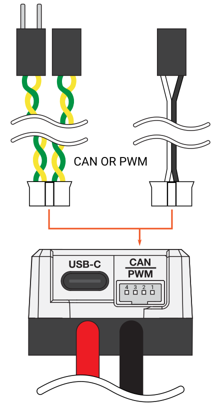
The driver for the REV ThroughBore encoder is straightforward since the encoder is wired to the Raspberry Pi using its white ABS wire. The absolute output is sent over the ABS wire through PWM. Another option for reading the encoder’s position is through its blue ENC A and yellow ENC B wires as a ‘Quadrature’ encoder. This approach may be more precise, although it is relative to the encoder’s startup position. We need the absolute output of the encoder, meaning the ABS wire was our only way to go. See the Datasheet here.
There is no sysfs interface for reading PWM inputs like there is for PWM outputs, so I had to implement it manually using the thunder::DigitalInput driver (Section 6.1.9).
Here is the PWM Pulse information for the REV ThroughBore encoder, found in the Datasheet:
- Period
- 1025μs
- Frequency
- 975.6Hz
- Pulse width range
- 1μs → 1024μs
The Pulse width range represents the angle of the ThroughBore between 0˚ and 360˚.
The driver creates a thread dedicated to reading inputs from the sensor.
First, the driver will wait until the pin input is 1 (the rising edge of the pulse). When it does, the driver will save the current time point and start waiting until the pin input is 0 (the falling edge of the pulse). If either of these wait sequences times out (takes longer than 102500μs), then the process gets restarted.
When the falling edge is detected, the driver will calculate the time elapsed between the rising and falling edges (the pulse width). As seen above, the pulse width will be between 1μs and 1024μs, representing the angle of the ThroughBore between 0˚ and 360˚.
Since this is working in microseconds, there is bound to be noise in the input. To reduce this noise and weed out unsatisfactory values, the driver uses an IIR (infinite impulse responses) LTI (linear time-invariant) filter to look at the moving average of the readings.
Question: Why was the PWM wire always calm and collected?
Answer:
Because it knew how to keep its pulse under control!
6.1.11: thunder::SparkMax Class
Hardware Driver Class
The PWM SparkMax driver is a simple PWM motor controller driver using sysfs.
Here is the PWM Pulse information for controlling SparkMax motor controllers over PWM, found in the Control Interfaces page of the SparkMax user manual (here).
- Full reverse
- 50μs → 1000μs
- Proportional reverse
- 1000μs → 1475μs
- Neutral
- 1475μs → 1525μs
- Proportional forward
- 1525μs → 2000μs
- Full forward
- 2000μs → 2500μs
- Valid pulse freq
- 50Hz → 200Hz
When initialized, the PWM channel is initialized by writing the desired channel number to the export file
/sys/class/pwm/pwmchip0/exportAs a result, a directory will be created at
/sys/class/pwm/pwmchip0/pwm<CHANNEL_NUMBER>The next initialization step is to write 1 to the enable file
/sys/class/pwm/pwmchip0/pwm<CHANNEL_NUMBER>/enable10000000 is written to the period file (\(1 \times 10^7\) μs, 100 Hz).
/sys/class/pwm/pwmchip0/pwm<CHANNEL_NUMBER>/periodTo set the speed of the motor controller, the duty cycle (in microseconds) is written to the duty_cycle file.
/sys/class/pwm/pwmchip0/pwm<CHANNEL_NUMBER>/duty_cycleThe motor controller has a ‘deadzone’ between 1475μs and 1525μs where the motor does not move. When controlling the motor using percent output (-1 to +1),
- -1 → 0
- 1000μs → 1475μs
- 0
- 1500μs
- 0 → +1
- 1525μs → 2000μs
Much of this control described above is split between the thunder::PWMMotorController and thunder::PWM classes instead of the thunder::SparkMax class, which inherits from the thunder::PWMMotorController class.
6.1.12: thunder::PressureTransducer Class
Hardware Driver Class
The thunder::PressureTransducer class controls the ADS1115 ADC (analog-to-digital converter). The pressure transducer used on this robot is analog, so the ADC board converts the signal to a digital for the Raspberry Pi to read.
The ADS1115 ADC operates over I2C; therefore, it is the most complicated driver I had to write for this robot. The Texas Instruments Datasheet that I referenced when writing the driver can be found here.
The driver handles I2C communication using sysfs. When the driver initializes, it opens the /dev/i2c-0 file. The file stays open until the driver class is destroyed.
The driver then binds the I2C address of the device (0x48) to the file descriptor using ioctl().
The register addresses on the device are 8-bit, and the register values are 16-bit. When reading a value from a register, the driver will write the 8-bit address, then read 2 bytes from the device for the value of the register. Writing to a register is similar; the driver will write the 8-bit address, then write the two bytes representing the desired register value.
The product page of the analog pressure transducer used on this robot can be found here.
Here is an overview of the analog pressure transducer:
- Output Voltage
- 0.5V → 4.5V
- Supply Voltage
- 5V
- Pressure Range
- 0 → 200 PSI
The pressure transducer is connected to the AIN0 pin of the ADC board.
On initialization, the ADC gets configured for use on this robot. Here is how the config register (at address 0x00) is formatted (a simplified version of section 9.6.3 of the Datasheet):
| Bit | Field | Description |
|---|---|---|
| 15 | OS | Operational status or single-shot conversion start This bit determines the operational status of the device. OS can only be written when in power-down state and has no effect when a conversion is ongoing. When writing: 0 : No effect 1 : Start a single conversion (when in power-down state) When reading: 0 : Device is currently performing a conversion 1 : Device is not currently performing a conversion |
| 14:12 | MUX[2:0] | Input multiplexer configuration These bits configure the input multiplexer. 000 : AINP = AIN0 and AINN = AIN1 (default) 001 : AINP = AIN0 and AINN = AIN3 010 : AINP = AIN1 and AINN = AIN3 011 : AINP = AIN2 and AINN = AIN3 100 : AINP = AIN0 and AINN = GND 101 : AINP = AIN1 and AINN = GND 110 : AINP = AIN2 and AINN = GND 111 : AINP = AIN3 and AINN = GND |
| 11:9 | PGA[2:0] | Programmable gain amplifier configuration These bits set the FSR of the programmable gain amplifier. 000 : FSR = ±6.144 V 001 : FSR = ±4.096 V 010 : FSR = ±2.048 V (default) 011 : FSR = ±1.024 V 100 : FSR = ±0.512 V 101 : FSR = ±0.256 V 110 : FSR = ±0.256 V 111 : FSR = ±0.256 V |
| 8 | MODE | Device operating mode This bit controls the operating mode. 0 : Continuous-conversion mode 1 : Single-shot mode or power-down state (default) |
| 7:5 | DR[2:0] | Data rate These bits control the data rate setting. 000 : 8 SPS 001 : 16 SPS 010 : 32 SPS 011 : 64 SPS 100 : 128 SPS (default) 101 : 250 SPS 110 : 475 SPS 111 : 860 SPS |
| 4 | COMP_MODE | Comparator mode This bit configures the comparator operating mode. 0 : Traditional comparator (default) 1 : Window comparator |
| 3 | COMP_POL | Comparator polarity This bit controls the polarity of the ALERT/RDY pin. 0 : Active low (default) 1 : Active high |
| 2 | COMP_LAT | Latching comparator This bit controls whether the ALERT/RDY pin latches after being asserted or clears after conversions are within the margin of the upper and lower threshold values. 0 : Nonlatching comparator . The ALERT/RDY pin does not latch when asserted (default). 1 : Latching comparator. The asserted ALERT/RDY pin remains latched until conversion data are read by the master or an appropriate SMBus alert response is sent by the master. The device responds with its address, and it is the lowest address currently asserting the ALERT/RDY bus line. |
| 1:0 | COMP_QUE[1:0] | Comparator queue and disable These bits perform two functions. When set to 11, the comparator is disabled and the ALERT/RDY pin is set to a high-impedance state. When set to any other value, the ALERT/RDY pin and the comparator function are enabled, and the set value determines the number of successive conversions exceeding the upper or lower threshold required before asserting the ALERT/RDY pin. 00 : Assert after one conversion 01 : Assert after two conversions 10 : Assert after four conversions 11 : Disable comparator and set ALERT/RDY pin to high-impedance (default) |
First, the driver sets the MUX field to 0 to tell the multiplexer to use the pressure transducer attached to pin AIN0 as a differential input rather than single-ended.
Next, the MODE field is set to 0 to put the device into continuous mode (no need to prompt the device to convert like single-shot). In continuous mode, the device will convert automatically every 8µs or so.
Next, the PGA field gets set to 1 for the gain of 4.096V. You might be asking: “Peter what are you doing?!?! The sensor will go up to 4.5V!!!.” That is correct; however, the fill tank will only ever pressurize to a max of 120PSI. At 4.096V, the pressure would need to be around 175PSI, which will never happen – don’t even think about 4.5V. Using the lower gain of 4.096V instead of 6.144V will give us better resolution, even if it does not matter too much.
Finally, the DR, COMP_MODE, COMP_POL, COMP_LAT, and COMP_QUE fields get set to their respective default values.
The configured 16-bit config value gets written to the config register at address 0x00.
When reading the pressure from the sensor, the driver reads the value from the conversion register at 0x01. Since the ADC is in continuous conversion mode, the register value is the most recent reading from the sensor. The driver then converts the analog value to a voltage, then converts that voltage to a 0-200 PSI reading.
6.1.13: thunder::LEDStrip Class
Hardware Driver Class
The thunder::LEDStrip driver controls the the WS2812 LEDs on the robot over PWM. Since LEDs are notoriously difficult to control over PWM (they require incredibly precise timing), the driver uses the rpi_ws281x C library.
TODO: Finish this section
6.1.14: Dashboard Server
- DashboardServer
- Header Source
- ConnectionManager
- Header Source
- HTTPRequest
- Header Source
- HTTPResponse
- Header Source
The main control program runs a HTTP/1.1 server to host the Dashboard page. To learn about the Dashboard itself, see Section 6.2.
6.1.14.1: Connecting to the Dashboard Server
In a web browser, go to the IP address of the Raspberry Pi,
http://<Raspberry_Pi_IP_Address>/Or, using mDNS (Section 8.2), use the hostname followed by the “.local” domain to resolve the IP address. By default (Section 7.6), the hostname should be ‘bizarrohomer’,
If the server is hosted on an alternate port (Section 6.1.14.3), append the address with a colon followed by the port number.
http://bizarrohomer.local:8080/
6.1.14.2: Dashboard Server Directory
The server hosts the directory
/var/frc1511/BizarroHomer/dashboard/Anything and everything in that directory is available on the site (as long as the file is within the max content size specified in Section 6.1.14.5.
6.1.14.3: Dashboard Server Port
By default, the server hosts on port 80 (this requires elevated privileges). To supply an alternate port, add the port number to the program’s command-line arguments. For example, this runs the HTTP/1.1 server on port 8080,
$ ./BizarroHomerMain 8080
6.1.14.4: Dashboard Server Requests
The server is very basic - only GET methods are dealt with, everything else will return a 405 Method Not Allowed response.
When a request to /coffee/ is made, the server returns a 418 I’m a Teapot response. Alternatively, when a request to /tea/ is made, the server returns some tea.
All HTTP request headers are completely ignored 😎.
6.1.14.5: Dashboard Server Responses
HTTP responses from the server look like this:
HTTP/1.1 <The_Status>
Connection: keep-alive
Server: Bizarro Homer Diagnostic Server
Content-Length: <The_Content_Length>

<The_Content>
The maximum content length is 81920 bytes. Any file bigger gets truncated. Sorry, gotta conserve memory.
6.1.14.6: Dashboard Server Connections
The server can handle a maximum of four simultaneous connections.
The server will terminate a connection with a client after ten seconds of inactivity.
6.2: Dashboard
The Dashboard is a webpage hosted by the main robot program that contains debug information about the robot. See Section 6.1.14.1 for information about how to connect to the Dashboard.
6.1.1: Values Page
The /values/ page presents a key-value pair list (similar to Network Tables in FRC). The values update every 500ms.
Each mechanism class in the program has a send_feedback function, which uses the DashboardServer class to update values periodically. For example, the ShooterBarrel class (Section 6.1.7) may send “Barrel_Angle” with the angle of the barrel.
6.1.2: Main Program Output Page
The /main/ page contains the stdout and stderr outputs of the main program. The page updates every 500 milliseconds.
Section 7: Hardware Overview
7.1: CAN ID Assignments
| ID | Subsystem Name | Component Type | Brake or Coast | Description | PDP ID | Breaker Amps |
|---|---|---|---|---|---|---|
| 0 | PDP | CTRE PDP | N/A | Power Distribution Panel | N/A | N/A |
| 21 | Shooter Rotation | CTRE Falcon 500 | Brake | Rotate the shooter | 12 | 40A |
| 22 | Shooter Pivot Left | CTRE Falcon 500 | Brake | Pivot the shooter | 01 | 40A |
| 23 | Shooter Pivot Right | CTRE Falcon 500 | Brake | Pivot the shooter | 00 | 40A |
7.2: PDP Assignments
| Component | Breaker | ID | ID | Breaker | Component |
|---|---|---|---|---|---|
| Shooter Pivot Left | 40A | 00 | 15 | 40A | Right Drive 1 |
| Shooter Pivot Right | 40A | 01 | 14 | 40A | Right Drive 2 |
| Left Drive 1 | 40A | 02 | 13 | ||
| Left Drive 2 | 40A | 03 | 12 | 40A | Shooter Barrel Rotation |
| 04 | 11 | ||||
| 05 | 10 | ||||
| 12V Relay → Fill Solenoid | 20A | 06 | 09 | ||
| 12V Relay → Shoot Solenoid | 20A | 07 | 08 |
| ID | 16 | 17 | 18 |
|---|---|---|---|
| Component | Raspberry Pi | CTRE VRM |
7.3 Raspberry Pi Pinout
| Component | Pin Type | ID | ID | Pin Type | Component |
|---|---|---|---|---|---|
| Barrel ThroughBore encoder | 3V3 Power | 1 | 2 | 5V Power | |
| I2C ADC Module + Analog Pressure Transducer | GPIO 2 (SDA) | 3 | 4 | 5V Power | |
| I2C ADC Module + Analog Pressure Transducer | GPIO 3 (SCL) | 5 | 6 | Ground | |
| GPIO 4 (GPCLK0) | 7 | 8 | GPIO 14 (TXD) | ||
| 2x Relay | Ground | 9 | 10 | GPIO 15 (RXD) | |
| 12V Relay + Fill Solenoid Valve | GPIO 17 | 11 | 12 | GPIO 18 (PCM_CLK) | WS2812 LED Strip |
| 12V Relay + Shoot Solenoid Valve | GPIO 27 | 13 | 14 | Ground | WS2812 LED Strip |
| GPIO 22 | 15 | 16 | GPIO 23 | ||
| 2x Relay | 3V3 Power | 17 | 18 | GPIO 24 | Barrel ThroughBore encoder |
| GPIO 10 (MOSI) | 19 | 20 | Ground | Barrel ThroughBore encoder | |
| GPIO 9 (MISO) | 21 | 22 | GPIO 25 | ||
| GPIO 11 (SCLK) | 23 | 24 | GPIO 8 (CE0) | ||
| Ground | 25 | 26 | GPIO 7 (CE1) | ||
| GPIO 0 (ID_SD) | 27 | 28 | GPIO 1 (ID_SC) | ||
| GPIO 5 | 29 | 30 | Ground | Drive Left - 2x Spark Max | |
| GPIO 6 | 31 | 32 | GPIO 12 (PWM0) | Drive Left - 2x Spark Max | |
| Drive Right - 2x Spark Max | GPIO 13 (PWM1) | 33 | 34 | Ground | Drive Right - 2x Spark Max |
| GPIO 19 (PCM_FS) | 35 | 36 | GPIO 16 | ||
| GPIO 26 | 37 | 38 | GPIO 20 (PCM_DIN) | ||
| Ground | 39 | 40 | GPIO 21 (PCM_DOUT) |
7.4 VRM Assignments
| Component | Output Rail | Output Rail | Component |
|---|---|---|---|
| 12V/2A | 5V/2A | Left WS2812 LED Strip | |
| 12V/2A | 5V/2A | Right WS2812 LED Strip | |
| 12V/500mA | 5V/500mA | I2C ADC Module | |
| 12V/500mA | 5V/500mA | Analog Pressure Transducer |
7.5 Electrical Wiring
7.5.1: CAN Chain
The CAN chain runs in the following order:
- Raspberry Pi
- Shooter Barrel Falcon 500
- Right Shooter Pivot Falcon 500
- Left Shooter Pivot Falcon 500
- Power Distribution Panel
The CANable 2.0 USB-CAN adapter is plugged into one of the USB ports on the Raspberry Pi. This facilitates CAN Bus communication on the Raspberry Pi, and serves as the beginning of the CAN chain.
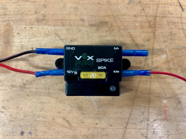
7.5.2: Solenoid Valves
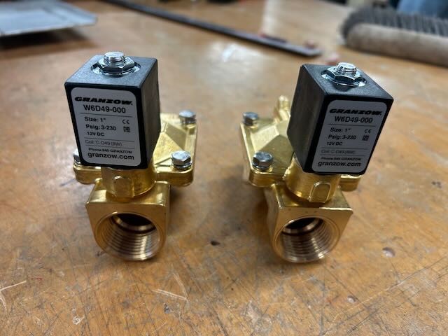
The two solenoid valves on the robot are 12V; however, the GPIO pins on the Raspberry Pi can only output 3.3V. To get around this, we use two VEX Spike H-Bridge Relay Modules to relay the 3.3V signal of the Raspberry Pi to a 12V signal for the solenoid.
7.5.3: Drivetrain
The drivetrain is powered by 4 Neo motors (two on each side), each controlled by a SparkMax motor controller. Since the two motors on each side are geared together, the signal PWM wires for both their SparkMaxes are soldered together to control them as one. The resulting two PWM signal wires get plugged into the PWM0 and PWM1 Raspberry Pi pins.
7.5.4: Shooter Barrel
A Falcon 500 motor is used to control the rotation of the barrel, and a REV ThroughBore encoder is used to read its angle. The ThroughBore is wired using its ABS wire, and controlled as a duty-cycle encoder (as opposed to using its ENC A and ENC B wires as a quadrature encoder).
7.5.5: Pressure Transducer
Since the pressure transducer is analog, we need an ADC board to conver the analog signal to a digital signal for the Raspberry Pi to read. The Pressure Transducer and the ADC board are powered using the 5V/500mA rails on the VRM. The Pressure Transducer’s signal wire goes to the AIN0 pin on the ADC board. The ADC board is wired to the Raspberry Pi over I2C.
7.5.6: Raspberry Pi
The Raspberry Pi is powered using a 12V to 5V 3A step-down convertor connected to the PDP.
7.6: Raspberry Pi
The Raspberry Pi used to control the robot is a Raspberry Pi 3 Model B.
Here is the user information:
- Hostname
- bizarrohomer
- User
- pi
- Password
- The first and last name of the team's newest programming mentor, lowercase and no spaces.
As of writing this (July 24th, 2023), the operating system information is:
- OS
- Raspberry Pi OS Lite
- Release
- May 3rd 2023
- Kernel version
- 6.1
- Debian version
- 11 (Bullseye)
OS downloaded from here.
7.7: CTRE Hardware
The robot uses three CTRE Falcon 500 motors and one CTRE Power Distribution Panel. These devices operate over the CAN chain and can be tricky to get working. This section outlines the process of getting them working and troubleshooting them.
7.7.1: Falcon 500 FRC Locked
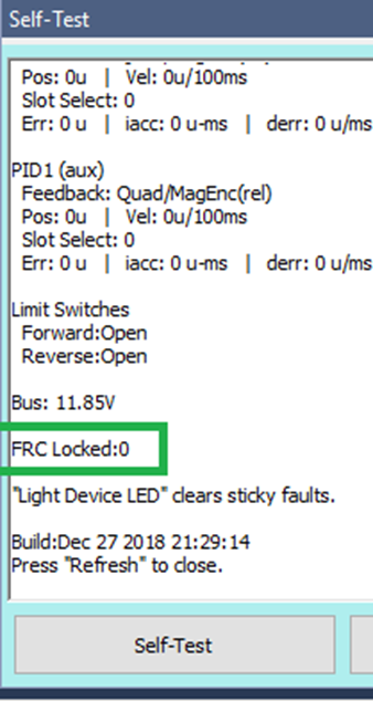
If a Falcon 500 was previously used with a roboRIO (at any time ever), then a (really annoying) property called ‘FRC Locked’ will be set to 1. This prevents the device from being controlled by anything except a roboRIO.
To check this, get a Self-test Snapshot on the TalonFX motor controller in Phoenix Tuner (see Section 7.7.2 for how to run Phoenix Tuner).
If the device is FRC Locked (=1), use factory default in the Config tab to clear the state. Use the config export tool if you need to keep your config settings.
7.7.2: Phoenix Tuner
To update the firmware or configure settings of CTRE hardware components, use the CTRE Phoenix Tuner app (download here).
The main control program (Section 6.1) hosts the Phoenix Diagnostic Server on port 1250. This lets the Phoenix Tuner connect with the robot.
First, connect an ethernet cable from the Raspberry Pi to the computer with Phoenix Tuner installed, or connect the Raspberry Pi and the computer to a similar network.
Inside Phoenix Tuner, find the ‘Diagnostic Server Address or Team Number’ box. Enter the IP address of the Raspberry Pi, or use a ‘.local’ mDNS address (Section 8.2).
Make sure that the port number is 1250.
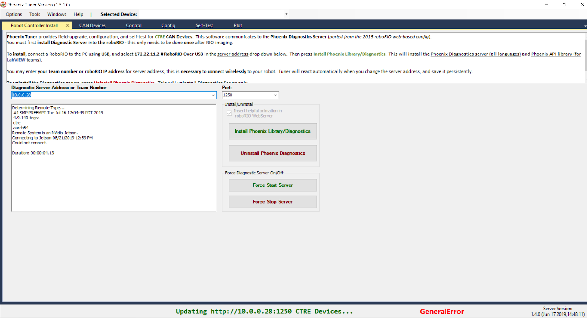
If everything is good, the bottom should be green, saying something like
Updating http://bizarrohomer.local:1250 CTRE Devices… Ok
The devices should show up in the CAN Devices tab.
Section 8: Raspberry Pi Stuff
8.1: Raspberry Pi Setup
Here are the steps for setting up a new Raspberry Pi image.
8.1.1: Install Required Tools
The required tools
- BlueZ
- Git
- CMake
- SDL2
- CAN Utils
$ sudo apt-get install bluez git cmake libsdl2-dev can-utils8.1.2: Enable and Verify CAN
The setup will differ depending on which CAN adapter is being used.
- For the Waveshare RS485 CAN HAT, add these lines to
/boot/config.txtdtparam=spi=on dtoverlay=mcp2515-can0,oscillator=12000000,interrupt=25,spimaxfrequency=2000000 - For a CANable 2.0 adapter, add these lines to
/etc/network/interfacesallow-hotplug can0 iface can0 can static bitrate 1000000 txqueuelen 1000 up /sbin/ip link set $IFACE down up /sbin/ip link set $IFACE up type canThis enables hot swapping, which seems to have good results.
To validate the CAN network, run
$ ifconfigLook for an entry named can0.
See all incoming CAN traffic by running
$ candump can08.1.3: Enable PWM
Enable PWM0 and PWM1 by adding the following line to /boot/config.txt.
dtoverlay=pwm-2chan,pin=12,func=4,pin2=13,func2=48.1.4: Build and Install Program
- Clone the repository
$ git clone https://github.com/frc1511/BizarroHomer.git - Initialize and update submodules
$ git submodule init $ git submodule update - Enter the project directory, then build the project using CMake
$ cmake -H . -B build -DCMAKE_BUILD_TYPE=Release $ cmake --build build/ - Install everything
$ sudo cmake --install build/ - Restart the Raspberry Pi. The systemd service should automatically start up.
8.2: Using mDNS to Resolve IP Address
mDNS (Multicast DNS) is a protocol that enables devices on a local network to discover each other by resolving their hostnames to IP addresses without needing a centralized DNS server. It is useful when connecting to the Raspberry Pi without knowing its IP address.
Windows does not have mDNS support out of the box. Get it by installing Apple’s Bonjour Print Services for Windows here.
Nothing needs to be done on the Raspberry Pi side.
To resolve the Raspberry Pi’s IP address using mDNS, use the Raspberry Pi’s hostname (‘bizarrohomer’ by default, Section 7.6) followed by the ‘.local’ domain, for example
bizarrohomer.local8.3: Remoting into the Raspberry Pi
To get a remote shell, use SSH with the user (pi by default, Section 7.6) and the IP address of the Raspberry Pi,
$ ssh pi@<Raspberry_Pi_IP_Address>Or you can use mDNS to resolve the IP address using the hostname followed by the ‘.local’ domain.
$ ssh pi@bizarrohomer.localYou should be prompted for the password for the user (Section 7.6).
8.4: Transferring files to and from the Raspberry Pi
Use the SCP command to transfer files to and from the Raspberry Pi. SCP works the same as SSH (Section 8.3) in which it needs the user and the IP address of the Raspberry Pi.
To copy a file to the Raspberry Pi,
$ scp file.txt pi@bizarrohomer.local:/home/pi/file.txtTo get a file from the Raspberry Pi,
$ scp pi@bizarrohomer.local:/home/pi/file.txt file.txt8.5: Raspberry Pi Internet Access
Typically, connecting the Raspberry Pi to a wireless network is easy as editing the /etc/wpa_supplicant/wpa_supplicant.conf file with the network’s SSID and password,
country=us
update_config=1
ctrl_interface=/var/run/wpa_supplicant

network={
  scan_ssid=1
  ssid="<The_SSID>"
  psk="<The_Password>"
}
However, this will not work with the Penfield CSD Guest network due to the captive portal used to authenticate devices. This captive portal still haunts Peter’s nightmares.
Also, do not plug the Raspberry Pi into an ethernet port on the wall. The IT people do not like that very much.
Obviously, you could use a hotspot, although there is a workaround to use the school’s Wi-Fi.
- Get two Laptops.
- One for sharing the Wi-Fi, and the other for remoting into the Raspberry Pi.
- Get an Ethernet Switch
- Plug the Raspberry Pi and the two laptops in.
- Connect one laptop to the guest network and configure it to share Wi-Fi through its ethernet port…
- Open Network & Internet page in Settings and select Change adapter options.
- Right click on the Wi-Fi adapter and select Properties.
- Select the Sharing tab.
- Check the checkbox labeled “Allow other network users to connect through this computer’s Internet connection” and select the Ethernet adapter connected to the switch.
- If the checkbox is already checked, uncheck it and check it again. It never seems to work if you don’t do this.
8.6: Pairing a New DualShock4 Controller
Pairing a new controller is a bit involved and hopefully not necessary. If a paired controller does not connect, check it has a charged battery.
As a reminder, only attempt to use DualShock4 controllers with this robot. Other controllers may have different button/joystick interfaces. Using another kind of controller could result in rearranged buttons or unexpected inputs. Be cautious, and do not blame Peter’s code if something stops working.
Here are the instructions for pairing a controller…
First, remote into the Raspberry Pi (Section 8.3).
Put the DualShock4 controller into pairing mode by holding down the Share Button and the PlayStation Button until the LEDs start flashing white.
Next, startup bluetoothctl.
$ bluetoothctlTurn on bluetooth and scan for devices.
[bluetooth]# power on
[bluetooth]# agent off
[bluetooth]# agent NoInputNoOutput
[bluetooth]# default-agent
[bluetooth]# scan on
The Raspberry Pi should start listing detected devices in the vicinity.
When the “Wireless Controller” appears in the scan, pair to it using its Bluetooth address.
[bluetooth]# pair XX:XX:XX:XX:XX:XX
[bluetooth]# trust XX:XX:XX:XX:XX:XX
Now the controller should automatically connect to the Raspberry Pi when it turns on.
To list all paired devices,
[bluetooth]# paired-devices